Build the Ultimate Motorized Bicycle
Bicycle Motor Installation
The most economical and fun motor vehicles are bicycles with a motor fitted. These instructions guide you step by step on how to build a motorized bike.
Best practice guidelines help you through the process of safely fitting an bicycle motor kit onto your bike.
Before installing the bicycle motor
There are a couple of things to check before fitting a bicycle with gas motor.
A good installation starts with knowing which bicycles are easy to install motors on. It may save a lot of money, time, and effort, purchasing a suitable bicycle rather than trying to bend the motor to fit your bicycle.
If you have never installed a bicycle motor kit before, if your DIY skills are not up to par, or if you simply don’t have a good selection of tools, then you may want to refer to our section on choosing the correct bicycle. The article could make all the difference.
If you are confident that you have the right bicycle, you should check the parts in the motor kit that you have purchased.


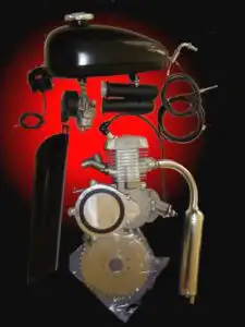
Bicycle motor kit - Parts List
1. Fuel Tank
2. Carburetor and air filter
3. Throttle control & cut-out switch with leads and left side handle bar grip.
4. Bicycle motor & mounting clamps
5. Handle bar mounted clutch lever
6. Clutch cable and fittings.
7. Throttle cable.
8. Muffler pipe
9. Ignition cdi box.
10. Rear sprocket
11. Drive chain and chain tension roller.
12. Bag of hardware and fittings.
13. Chain guard.

Amazon bicycle motor kits
Most bicycle motor kits are purchased from Amazon suppliers. The first rule of how to install a motor on a bicycle is to check that everything in the motor kit is OK and nothing has been damaged in transit.
If you ordered any extra items, make sure they are there. You should also check that the motor is the model you ordered. A rule of thumb for engine capacity is that 50cc 2-stroke engines have 10 mm head bolts and 80cc motors have 16 mm head bolts.
If any parts are missing, you should contact your supplier straight away as transactions are usually finalized 30 days after the order was placed.
Before you go further with how to install a motor on a bicycle, you should familiarize yourself with the various items in the kit and what they are for.
Examine how the components interact with each other and where they could fit on the bike. Thinking things through and planning how things may fit will make the job much easier down the track.
Installing the bicycle motor
Rear sprocket installation
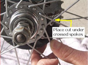
1. Find the two rear sprocket rubber packing pieces. Cut only one of them between the drilled holes, as shown image.
2. Place the cut packing piece inside the spokes.
3. Place the other packing piece on the outside of the spokes.
4. Place the metal support segments against the rubber inside the wheel and the sprocket on the outside, with the teeth offset inwards. That is, the step on the teeth is towards the wheel spokes. Overlap the split of the inner rubber with one of the plates (see images). Bikes with large tires may need to reverse the sprocket. Reversing the sprocket will provide a little more distance between the sprocket teeth and the spokes which can help the chain clear the rear tire.
5. Push the nine bolts through the sprocket, outer rubber, the inner rubber, and finally the support pieces.
6. Place washers and nuts on the bolts and tighten them so the assembly is loosely held together with light pressure on the spokes. All nuts need to have the same amount of thread protruding.


Sprocket mount from inside the rear wheel
This picture shows the sprocket mounting from the inside of the rear wheel
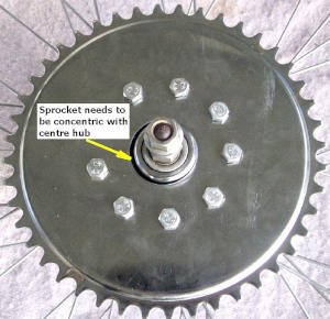
Center the rear sprocket
Try to get the sprocket as close to the center of the wheel as possible. If the sprocket is not centered, the chain will stretch faster and will be difficult to adjust with the chain tensioner.
7. Align sprocket and center hub so the gap is even all round. Use a block of wood and a hammer against the teeth to tap the sprocket into position, if necessary. (Image shows misaligned sprocket).
8. Tighten the nuts and bolts 2 full turns in a criss cross or star pattern and check the hub alignment again and adjust if necessary Tighten the nuts and bolts another full turn moving in a star fashion across the sprocket.
9. Repeat this process twice more, checking the alignment as you go. The nuts should now be tight enough to hold the sprocket firmly against the spokes but have some flexing in the drive direction.
10. Spin the wheel and check that the sprocket runs true. A run-out of more than 1/2” may cause the chain to bind, jam or jump off the sprocket.
Correct any side to side wobble by tightening the nuts where the sprocket is further from the spokes and slackening the nuts a little on the opposite side. This will pull the sprocket back into alignment.
If there is a gap between the two rubbers, tighten all the nuts evenly, until the rubbers are just touching.
Do not over tighten the nuts. The rubbers provide a degree of shock absorption from the chain drive. If the rubbers are over tight there will be less “give” in the sprocket and a greater likelihood that you could pull spokes from the rim while riding.
If there is still some run-out, use a large shifting spanner to bend the section of sprocket giving trouble. You do not need to use much force to do this.

Re-fit the bicycle wheel
11. Place the wheel in the bike frame and install it as indicated in the bicycle instruction manual. At this time leave the axle retaining nuts finger tight, they will be tightened later when the drive chain alignment is set. Check the wheel and sprocket run true and adjust if necessary. Make any further adjustments if required.
mounting the motor
Do not use "bolt through the frame" large frame adaptors
Minimize engine vibration
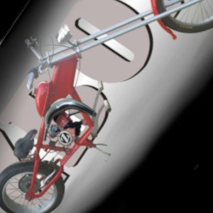
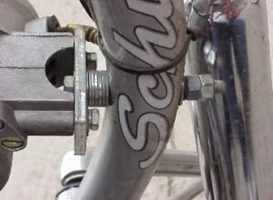
Vibration is a serious concern with all single cylinder bicycle engines, so it is a good idea to use rubber pads (about 3 mm thick) between the mounts, the clamps and the frame. The tube failure in the image was due to poor installation technique.
Many bicycle engine kits supply a “bolt through the frame” to assist fitting to large frame bikes. This practice is illegal in many country’s as it weakens the bicycle frame and is potentially dangerous for the rider. This means no drilling, cutting, bending, grinding or welding. This is why the bicycle motor and fuel tank mounts are designed as they are.
Fitting the bicycle motor
If the motor is not mounted securely, you will have constant problems with the motor twisting in the frame. The result will be broken engine mounts and studs. In addition, the chain tension and alignment will be problematic. Taking extra care with the mounting process will save hours of work, frustration and money.
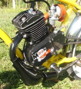
This image shows the engine mounted on the bike. Notice the intake inlet clearance. Always mount air intake with inlets down! If you need to, you can put the air box on a grinder and cut down on the inlet tubes a little to make sure they clear the frame. If you use the spacer on the front engine mount, usually this provides enough clearance. You may need to file down any water bottle screw mounts if they protrude and are in the way of a engine mount.
Check how the bicycle motor fits in the frame
Before you stat the installation, check how the motor, carburetor and muffler will be positioned
Position the bicycle motor
This is the most important part of how to install a motor on a bicycle. Secure mounting the engine will prevent many problems developing when riding the bike.
1. Offer the motor up to the frame to make sure it will fit. Put the carburetor assembly temporally in place to check for clearance of the air filter and the throttle cable. Also remember to check the drive chain alignment and do a trial fit of the exhaust pipe. It needs to clear the ‘down tube’ and not be struck by the LH pedal.
Note: It is rare that the motor will go straight into the frame. The following guidelines will help you avoid the
usual pitfalls when installing the motor.
• The carburetor needs to be horizontal or tilted up or down to a maximum of 10° (see image)
• It is best to mount the motor as far forward as possible. If the front tube is larger in diameter a large tube mounting kit for tube diameters up to 3″ are available from bicycle motor retailers and hardware stores.
Mount the motor high enough in the frame to clear any controls or brackets on the Seat Stay (see image above right and center).
• Rework the mounts so they are a good fit in the frame. Adding rubber pads (about 1/8” thick) helps reduce engine vibration and helps the mounts to grip the frame. Spacers and longer mounting studs are available from retailers.
NOTE: The rear engine mount must always be at right angles to the seat stay
• Do as little re-working of the front mount as is possible, better to re-arrange the rear mount to suit the frame.
(See images for ideas. If you need further help, contact us via the blog feedback page.) Make sure the chain will clear the bike frame and run straight between the two sprockets. Moving the motor mounting position up or down and leaning it a small amount to one side may, solve this problem.
• Remove the three screws retaining the sprocket cover (be careful not to loose the small bar and ball sitting in the center of the sprocket shaft), and using a piece of cord to check where the chain will sit, which will give you an idea of how much clearance you have.
2. After making the necessary modifications and adjustments, mount the engine into the frame. The mass of the motor and the vibration created when it is running can cause havoc. Snug fitting mounts and clamps, together with firmly secured (but not over-tight) nuts, are essential.
Check the nuts frequently for security after the first few runs and any time there appears to be a change in engine vibration.

Installing the Drive Chain & Tensioner

Using the cord again, you can now align the front and rear sprockets. Place the cord along the teeth of the front sprocket and along the side of the rear sprocket. Change the angle of the wheel to get the cord to run parallel to the rear sprocket.
Now tighten the rear wheel retaining nuts. The nuts need to be really tight because vibration and torque loads of the motor may cause the wheel to slip.

Fitting the chain
Wind the chain onto the drive sprocket using the spark plug socket.
Chain and tensioner
Fit the chain tensioner below the bottom section of chain.
How to put a motor on a bicycle - Fitting the Chain
First the length of the chain needs to be checked. Locate and remove the joining link of the chain. A pair of long nosed pliers will release and re-install the clip.
With the sprocket cover removed, feed one end of the chain up from under the sprocket and use the spark plug spanner to turn the sprocket clockwise as you feed in the chain.
Bring the chain just to the rear of the seat stay and pass the other section of chain over the rear sprocket to join up with the front section. For most installations the chain is about 5 to 7 links too long and will need to be shortened.
Some bikes need a short section added. The rivet can be removed using a hammer and punch or by using a ‘chain breaker’ which is a special tool made for the job. If you need help with this, Motor Cycle shops usually have the right tools available.
When deciding where to ‘break’ the chain, make sure you remove the link that will allow the joining link to re-assemble the chain and always go to the link that will end up with a slightly loose chain. An over tight chain simply will not work.
When the chain length is correct, install the chain.
WARNING: An over-tight chain is more likely to drop off the sprockets than a correctly aligned loose chain.
Fitting the Chain Tensioner
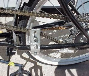
The image above shows the Idler Pulley parallel to the chain, however, the mounting bracket on the lower frame section is angled. The chain tensioner bracket has been twisted slightly to compensate for the angle of the frame arm. To achieve this, you may need to twist the top section of the mounting bracket.
NOTE: Different bikes have different frame angles (some with none at all) but you need to have the idler pulley mounted square to the chain. A vice and a large shifting spanner will do the job.
Use a couple of strips of rubber (old bike tubes work well) glued to the clamp area to prevent damage to the frame and to give the clamp extra grip. Fit the tensioner about 6″ in front of the rear axle. It is best to fit the tensioner nearer to the rear sprocket rather than close to the motor.
The clamp nuts and bolts need to be tight but be careful not to crush the frame. Some bikes have very little strength in this area so take care. An indication you are crushing the tube is when the torque on the nuts does not increase as you continue to tighten them.
Correct chain movement
Once the chain tensioner assembly is installed, adjust the pulley to obtain about 1″ of ‘droop’ at the center point of the top section of chain.
Wheel the bike around to check for the tightest point of the chain. This is where you need between 1/2″ – 1″ of droop.
NOTE: You may find the chain does not run over the front sprocket smoothly. Do not worry about this when the bicycle motor is new. Once the motor has been running for a few minutes this condition should disappear. Also the image above shows the use of pliers to remove and fit the clip on the joining link. Make sure the ‘nose’ (the rounded part) of the clip faces the direction of rotation of the chain, if not, it may flick off.
You can now re-install the Sprocket Cover. Ensure that the clutch arm points to the rear of the bike.

Bicycle motor controls
Remove the handlebar grips
1. Remove the hand grips from the handlebars. If you have access to compressed air, this can be used to blow air under the grips to help remove them. If you cannot get them off you will have to cut them off with a sharp knife.
2. If you have shifter controls, loosen the clamps and slide them inboard as far as possible. Do the same with the brake levers.

Brake and clutch levers
Position the brake lever below the clutch lever
3. Place the clutch control lever on the LH side of the bar horizontal to the ground.
4. Angle the Brake Lever to about 45 ̊ and tighten clamps on both levers.
5. Sit on the bike and see if you can comfortably grab the brake lever by putting your hand between the clutch lever and the handle bar. Now put your hand over the clutch lever and operate both levers. You need to be able to pull on
the brake while you operate the clutch with the first two fingers. Adjust the levers so you can do this.
If your clutch does not engage or disengage properly refer to our clutch setup guide.
Throttle twist grip
6. Take the clamp top-half off the throttle Control assembly and slide the assembly onto the bar. If it stops before it touches the brake lever clamp, you will need to be sure to slide the control back a little, to give the twist grip some clearance at the end of the handle bar to ensure it does not bind after installation.
The top clamp has a small, 1/4″ diameter spigot that is intended to locate the throttle assembly so the clamp will not turn when you twist the throttle. A 1/4″ hole needs to be drilled in the handle bar at about a 45 ̊ angle at the top front of the bar. This is where you need to measure how far from the end of the bar the hole has to be to ensure the end clearance needed for the grip to rotate freely is available.
7. Install the cable assembly into the clamp body and attach the cable to the twist grip. NOTE: leave about 1/10″ of thread when screwing the ‘elbow’ into the grip so the lock nut can be fitted.
8. Fit the assembly to the handle bar, install the screws, but leave them loose. It takes a little fiddling to get the inner cable in the correct position along with the grip and the clamp arrangement. There is a ‘stop’ inside the clamp assembly that the grip rests against when in the ‘idle’ position. By rotating the grip, you will feel this position and, once you have this located, you will find the throttle will turn freely. When the clamp halves are in the correct position (with the spigot engaged in the drilled hole) they will match up evenly. Until you get this right, do not tighten the screws! Do not force anything, with some care, this assembly will come together and the throttle twist grip will rotate freely.
9. Now the throttle assembly is installed you need to fit the grip on the LH side and tighten all the clamp screws.
NOTE: Sometimes the Handle Bar is a little short. A simple fix is to cut a length of dowel (a broom handle is ideal) and reduce a 1″ section so it can be driven into the handle bar, then cut the dowel to the length.

Fitting the clutch cable
Do not over tighten the cable as this can cause the clutch to slip.
The outer cable has the large spring fitted near the Mounting Post on the motor (see image). The outer cable and the fitting on the post must be in alignment.
Do not worry about the angle of the inner wire as it runs to the Actuation Lever, this does not cause any excessive friction or wear as is often supposed.
Re-fit the Inner Cable and attach the lug at the Control Handle end. Thread the inner cable through the mounting-post ferrule and fit the small spring over the cable wire.
Thread the cable through the clutch actuation arm and fit the cable lock, there should be about 2mm of free-play at the actuation arm, which equates to about 10mm at the control lever.
Note: Some levers have the Lock Screw mounted directly on them. In this case the small spring is not used.
When the installation is completed, clutch lever action should be firm but manageable.
Once you are happy the cable assembly is correct, cut the inner cable so there is about 100mm of wire showing. You can get cable ends from a bike shop that fits over the cable-end to protect it from fraying
The Clutch Cable installation is simple but there are a number of details that are often missed when deciding how to install a motor on a bicycle.
Incorrect setting can cause a heavy lever action and eventually failure of the cable. The image here shows the cable arrangement and small spring position. This example shows how to keep the cable as straight and as short as possible.
To install the cable, you need to find a path that is as short as possible to the Mounting Post on the motor. The image of the controls at the top of this page shows the clutch cable with a gentle curve from the lever to the side of the frame. This is to allow for the turning of the handle bar. Make sure all cables are long enough to handle a full turn of the bar in either direction.
Once you have decided how long the clutch cable leads to be, remove the inner cable and cut the outer cable to length. Do not cut the inner cable until you have completed the cable installation.

Gas Bicycle Engine tuning
We all want to squeeze some more performance from our bicycle engines. See some quick, simple and cheap tuning options that will have your bicycle tearing up the road.
At this stage of the motorized bicycle installation instructions, it is a good idea to ride the bike around to get a feel of the overall operation.
Check the clutch control lever releases and engages the clutch, and the locking button on the lever assembly holds the lever in the released position. Check the brakes and gears work and you can pedal the bike around without difficulty.
NOTE: At this stage of installing the bicycle motor, the chain may click and jump around.
Check the alignment and tension of the idler pulley and if all appears OK, do not worry about the ‘roughness’ at this time. It is probably caused by the chain and the small sprocket not matching well and, once you have ridden the bike for a few minutes, with the motor running, this will disappear.
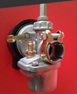
There are two types of carburetor that are typically provided with bicycle motor kits. The basic carburetor is the NT carb which has been provided with kits for over 20 years.
There is also a more sophisticated carburettor, the Rongtong carburettor, which has been supplied with premium bicycle motor kits since 2015.
The two carburetors are quite different in their construction. We have, therefore, provided links to separate articles on how to fit and tune these carburetors.
Click the images below to link to detailed sections of how to install a motor on a bicycle for the brand of carburetor supplied with your engine kit.

Fitting a sports carburetor
If your bicycle motor kit has the sports carburetor, click here for motorized bicycle installation instructions
Fitting an NT carburetor
If your bicycle motor kit has the NT carburetor, click here for additional section of how to put a motor on a bicycle.
Installing the Fuel Tank Assembly
Gluing rubber strips (old bicycle tubes work well) on the tank near the mounting studs and on the curved section of the clamps will help the tank grip the bike frame and stop it sliding around.
Install the tank close the steering head of the bike (with a gap from the front section of about 1 1/2″.
WARNING: Make sure the clamps are not in a position where they will clamp the cables to the frame. If the
cables run along the top of the frame, use an extra pair of clamps (available from retailers or you can make up a couple yourself) and 4 spacers (oversized nuts will work). This will give the cables clearance to operate normally when the tank is fitted.
Fit the Fuel Tap with the lever to the RH side of the assembly. Install the Fuel Line. WARNING: Do not use an additional Fuel filter. If one is supplied, discard it. It should have a gentle curve with no kinks. Cut it shorter if it looks like a cork-screw but be aware that the line shrinks over time so do not cut it too short. You can use small cable ties to hold the line in place if you want.
The nuts should be firm but just tight enough to stop the tank moving. Over tightening the nuts can pull the studs from the tank, causing fuel leaks.
WARNING: Do not force the screws. You will do permanent damage to the carburetor body. Be careful to get the choke locking lever in place. The spring tension on the lever can cause the cap to not seal correctly on the carburetor.
1. Remove the two screws retaining the cap and gently remove the assembly (see image).
2. Remove the spring and slide (see image).
Note the thumb is controlling the choke locking lever.
CAUTION: The choke locking lever may get caught in the body of the carburetor. Gently twist and wriggle the lever loose without damaging the gasket. Note that it is not essential to install the cable elbow.
3. If the cable elbow needs to be installed in the cap, fit it so there is about one thread visible above the cap.
4. Thread the cable through the elbow and fit the slide and spring assembly.
CAUTION: Take care not to damage the gasket. A torn gasket can cause air leaks that may upset the carburetor tuning.
5. Re-install the assembly as shown in the image.
6. Fit the screws and compress the spring until the cap sits squarely on the carb body, if the alignment is correct, the screws will freely screw into the body. If they are tight, then they are misaligned. Rock the cap a little to correct alignment.
Install the muffler, or expansion chamber, and tighten the nuts finger tight. Swing the lower section of the pipe to the RH side of the motor and tighten the nuts. Check the engine pipe is not touching the down tube of the bike, you need a minimum of 5 mm clearance. Turn the pedals to check the LH pedal also clears the pipe. The following methods may fix either or both of these problems.
• Drill out the mounting holes to 9 mm. You can then swing the pipe further to the right and slide it on the mount to the left. This small change is often enough to solve both problems.
• Angle the motor a few millimeters to the left and re-tighten the mounts.
• Make a wedged shaped spacer (use the gasket as a template) from a piece of aluminum and fit it with the thicker section on the RH side. You will need another gasket.
NOTE: The Idle Speed Screw is mounted on the RH side of the carbie body and is used to set idle speed. Turn it clockwise to increase speed. Idle speed should be between 2000 – 3000 RPM. This is a slow speed at which the motor will run constantly without stalling.
Fitting the Chain Guard
This is a very easy part of how to install a motor on a bicycle. It is not a legal requirement, but it is a good idea if you want to stay clean!
Locate the plate with the short screw & nut. Hold the rear of the guard to the ‘Back Stay’ and the nut on the motor holds the guard on the motor, which fits on the long screw that holds the rear of the Clutch Actuation Cover onto the motor assembly.
Offer the guard up to the screw on the motor and hook the notch over it. Loosely fit the washer and nut. Take the strap and bend it around the ‘Back Stay’ to form a letter ‘P’ with the holes together at the ‘leg’ of the letter. Refer to the picture to see how to arrange the guard.
Position it so the hole in the guard lines up with the holes in the ‘P’ clamp. Mark where the Back Stay fowls the guard, and cut out this section so you can clear the frame. You may need to do a little trimming at the other end. Once the trimming is done, fit the guard and bend and flex it so it clears the frame and chain.
Installing the CDI
Vibration and heat are the enemies of ignition systems. The CDI needs some rubber mounting material placed where it will be unaffected by engine and exhaust heat.
Use the clamp arrangement supplied to mount the module, or you can use a cable tie (both methods are shown). If you use a cable tie, sometimes the holes in the mount are undersized, so the same drill used for the throttle locating hole can be used to ease out the holes. Before installing the CDI, check the switch leads will reach the connectors on the CDI and the HT lead will reach the spark plug.
CAUTION: When installing a new spark plug, the sealing washer should be compressed. With the washer touching the head, you need to use the plug spanner to turn the plug about ¾ of a turn at which time it suddenly gets harder to tighten the plug. This is when the washer has compressed, so stop tightening the plug. Plug gap: 0.6 mm to 0.7 mm
Installing the Ignition
There are two key areas for the correct installation of the ignition system:
1. The CDI and the HT Lead and spark plug
NOTE: Plug gap is 0.6 – 0.7mm (.024” – 28”)
2. The ‘low tension’ wiring and the switch leads
Motorized bicycle wiring diagram
The handlebar controls (see image) shows the switch leads cable tied to the throttle cable as far as the
steering head and then follow the Clutch Cable down to the motor. Cable ties and spiral wrap (purchased from
automotive spare parts stores) are used to protect leads and hold them in place.
WARNING: Do not use
‘electrical tape’ or attempt to ‘waterproof’ the ignition system. All this will do is trap water in places where it will eventually cause failure. The spiral wrap allows air to circulate around the system and any moisture will soon dry out.
Riding in the rain is OK. It is very rare for an ignition system to fail when it gets wet.
The blue and black leads from the motor plug into the corresponding colored leads on the CDI.
The switch leads plug into the remaining two sockets, either way round. If there is a White lead from the motor, cut about 30mm off the end and tuck it down inside the insulating sleeve on the motor. This lead is no longer required.
It can be difficult to start an engine for the first time. It is easy to overlook a connector and flooding the engine is common.
If you need further help with starting, or want to know how to maintain your motorized bicycle, then click the link for further information.
Conclusion
A bicycle with motor offers a convenient and sustainable solution for urban commuting. These motorized bicycle fitting instructions cover just about everything you would want to know on how to install a motor on a bicycle.
We step through every detail of how to build a motorized bicycle and provide lots of tips on how to avoid the pitfalls.
It is important to purchase a good quality bicycle motor kit but, for ease of installation, it is essential that you choose the correct bicycle for the motor.